Description
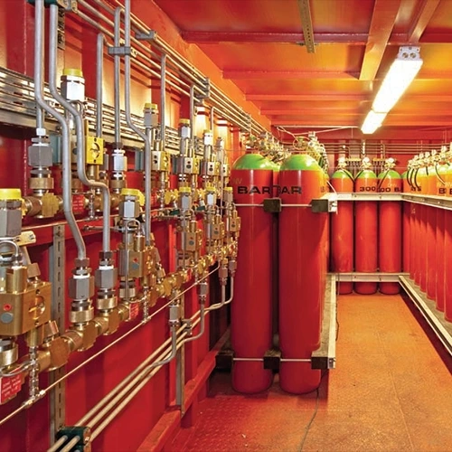
Gaseous fire suppression systems utilize clean agents that are typically non-toxic and odorless for fire suppression. These extinguishing agents are electrically non-conductive, colorless, and odorless, and are stored in special high-pressure containers. These systems are particularly useful in environments where water or foam could damage sensitive equipment, such as data centers and server rooms.
Details and Features
In case of detecting a fire, this system discharges gas, normally non-toxic and odorless, to the hazard area to suppress the fire. ….
Advantages
Gaseous fire suppression systems can be utilized in a wide range of environments and do not leave any residue, as implied by the term “clean agent.” These systems are cost-efficient, safe for both humans and the environment, and highly effective in fire suppression. Additionally, they ensure that the area remains clean after the fire is extinguished.
How is the fire extinguished?
As you may already know, the fire triangle has evolved into a fire tetrahedron, consisting of oxygen, heat, fuel, and a chemical chain reaction. Suppressing a fire involves eliminating one of these critical components. Gaseous fire suppression systems employ two approaches to extinguish fires: chemical interruption and oxygen reduction.
Chemical interruption
In this approach, the system suppresses the fire by cooling it down. This process occurs through the distribution of gases with higher thermal capacity than the fire, resulting in a reduction of temperature.
Reducing Oxygen
Reduction of oxygen is achieved through various mechanisms, including the discharge of gases such as nitrogen and argon, which lower the concentration of oxygen. By using these gases, the oxygen concentration is reduced to 15% in the area, preventing the fire from continuing and ultimately leading to complete extinguishment.

Types of gaseous fire suppression systems
Gaseous fire suppression systems fall into two main categories: Carbon Dioxide and Clean Agents. Each of these types has distinct approaches and special characteristics that make them suitable for various fire suppression needs.
Carbon Dioxide (CO2) fire suppression
In CO2 fire suppression systems, fires are extinguished by eliminating several elements of the fire triangle, with the main mechanism being the reduction of oxygen. These systems suppress fires by creating an environment with insufficient oxygen to sustain combustion. Despite their efficiency and simplicity, CO2 systems are harmful to the environment and can have adverse effects on the human body. Additionally, they are not as quick at extinguishing fires as some other methods.
Clean Agent fire suppression
Clean agent fire suppression systems use agents that are safe for both the environment and human health. These systems are popular for their efficiency and environmental friendliness. Compared to CO2 systems, the containers used for clean agents are larger and the suppression process takes longer. Clean agents fall into three main categories: Inert Gas (IG), Novec 1230, and Halocarbon.
Inert Gas
Inert gases, primarily composed of argon, nitrogen, and carbon dioxide, are used in fire suppression. The concentration of each gas in the final mixture depends on the fire characteristics and the type of occupancy. Inert gas systems are typically more expensive than other clean agent systems and are therefore usually installed in small spaces. These systems take about 60 seconds to completely flood the protected area.
Novec 1230
Novec 1230 is a pressurized gas stored in containers similar to pressurized nitrogen. It requires only 10 seconds to fully flood the protected area. When pressurized, Novec 1230 is in liquid form but discharges as a gas. This system extinguishes fires through two main mechanisms: heat elimination and inhibiting the fire’s chemical chain reaction.
Halocarbon
Halocarbon systems are electrically non-conductive and have a fast discharge time of approximately 10 seconds. These gases have minimal destructive effects on people and equipment. Halocarbons are categorized into two main types:
HFC – 125
This gas is a colorless, odorless and electrically non-conductive and is also environment-friendly. Therefore, it is popular among fire engineers.
FM200
FM200, also known as HFC-227EA, is the best substitute for halons as it has no harmful effects on the atmosphere. Its chemical formulation is heptafluoropropane, and it extinguishes fires through heat absorption. Some advantages of this fire suppression system include high reliability, compact containers, fast reaction time (less than 10 seconds), simple refilling process, and cost efficiency.
Gaseous fire suppression system components
An automatic gaseous fire suppression system consists of three main components: the high-pressure container, the system actuator, and the piping, valves, and nozzles that deliver the extinguishing agent to the protected area.
Gaseous fire suppression system application
As previously mentioned, automatic gaseous fire suppression systems are typically installed in environments containing sensitive equipment, where the use of water or foam sprinklers could cause damage. Such environments include data centers, server rooms, power and control rooms, museums, radiology centers, archives, libraries, and motor rooms.
Comparing gaseous and water fire fighting systems
Automatic gaseous and water-based fire fighting systems are both popular choices for suppressing or controlling fires, selected based on their specific features and the advantages and disadvantages they offer for particular scenarios.
While water-based fire fighting systems can effectively control fires, they are slower compared to gaseous systems, which can suppress a fire within 10 seconds. This slower response makes water-based systems less efficient for scenarios such as libraries and museums, where water could damage the facilities. In contrast, automatic gaseous fire suppression systems can be utilized in all types of environments.
After successfully controlling a fire with water-based systems, thorough cleaning is required to restore the area to its operational state, causing the facilities to remain non-operational for several hours. On the other hand, gaseous systems eliminate this downtime, as no cleaning is necessary following fire suppression.
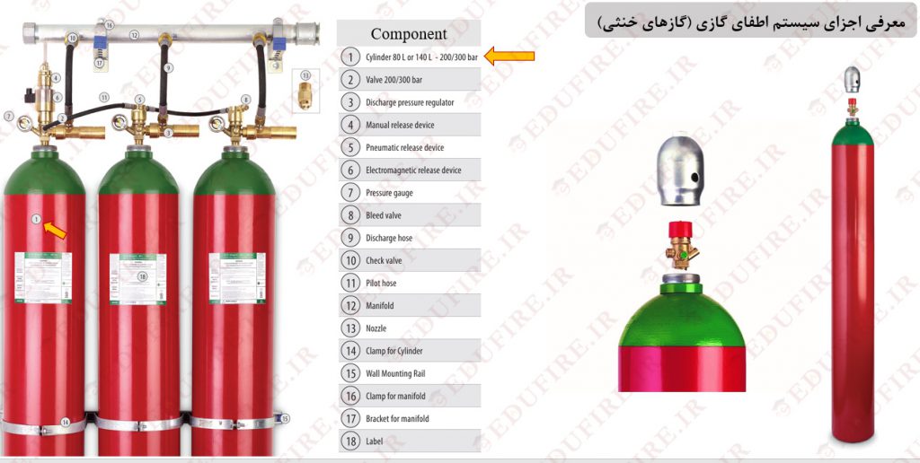
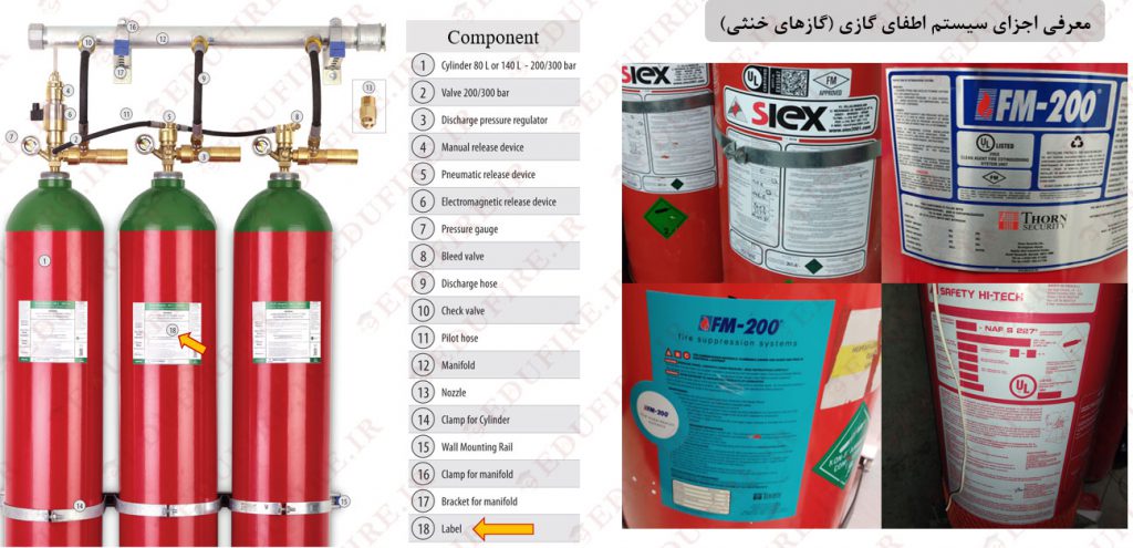
Gaseous fire suppression components
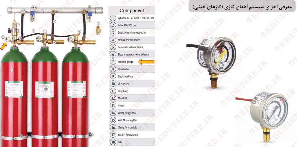
- Cylinder: Gaseous fire suppression cylinders are typically manufactured in nominal capacities of 80 and 140 liters, with pressure ranges from 200 to 300 bars.
Note: For some manufacturers, the pressure is limited to 150 bars.
Note: Some manufacturers offer cylinders in capacities other than 80 and 140 liters. For example, Rotarex manufactures cylinders with a 67-liter capacity.
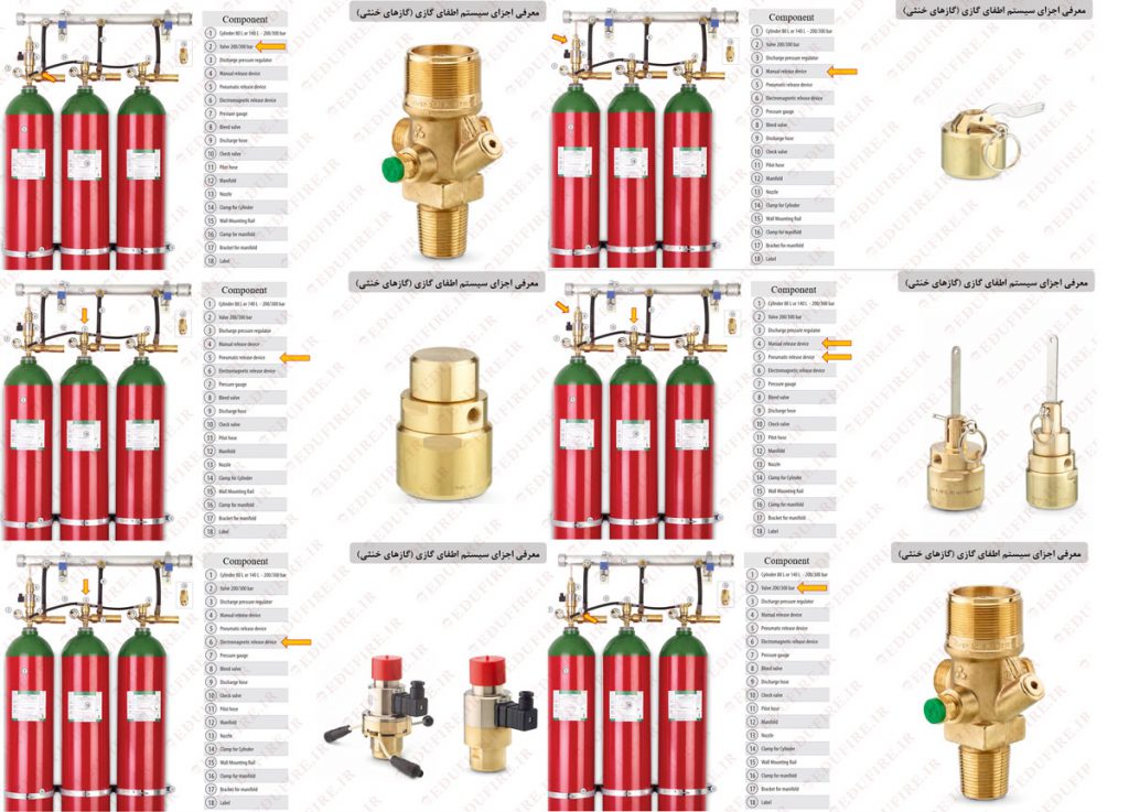
- Cylinder Valve: The cylinder valve is one of the most critical components of the system. It is responsible for maintaining the agent under pressure inside the container and can be actuated through four different mechanisms:
- Electrical: Using a solenoid or electromagnetic release device.
- Pneumatic: Using a pneumatic release device activated by the pressure from a pilot or master cylinder.
- Solenoid-Manual: Using the manual handle on the solenoid valve.
- Pneumatic-Manual: Using the handle on the pilot cylinder.
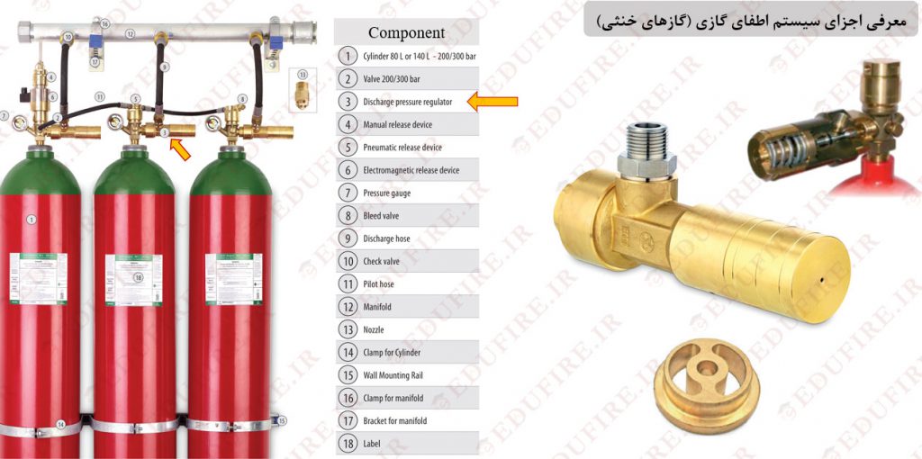
- Discharge pressure regulator: The discharge pressure regulator is installed at the outlet of IG system cylinders and reduces the outlet pressure. This enables the use of components with lower working pressure, significantly reducing costs. However, some manufacturers may not install this component on the cylinder, or the buyer may choose to exclude it from the material list. In such cases, the necessary pressure drop can be achieved using orifices.
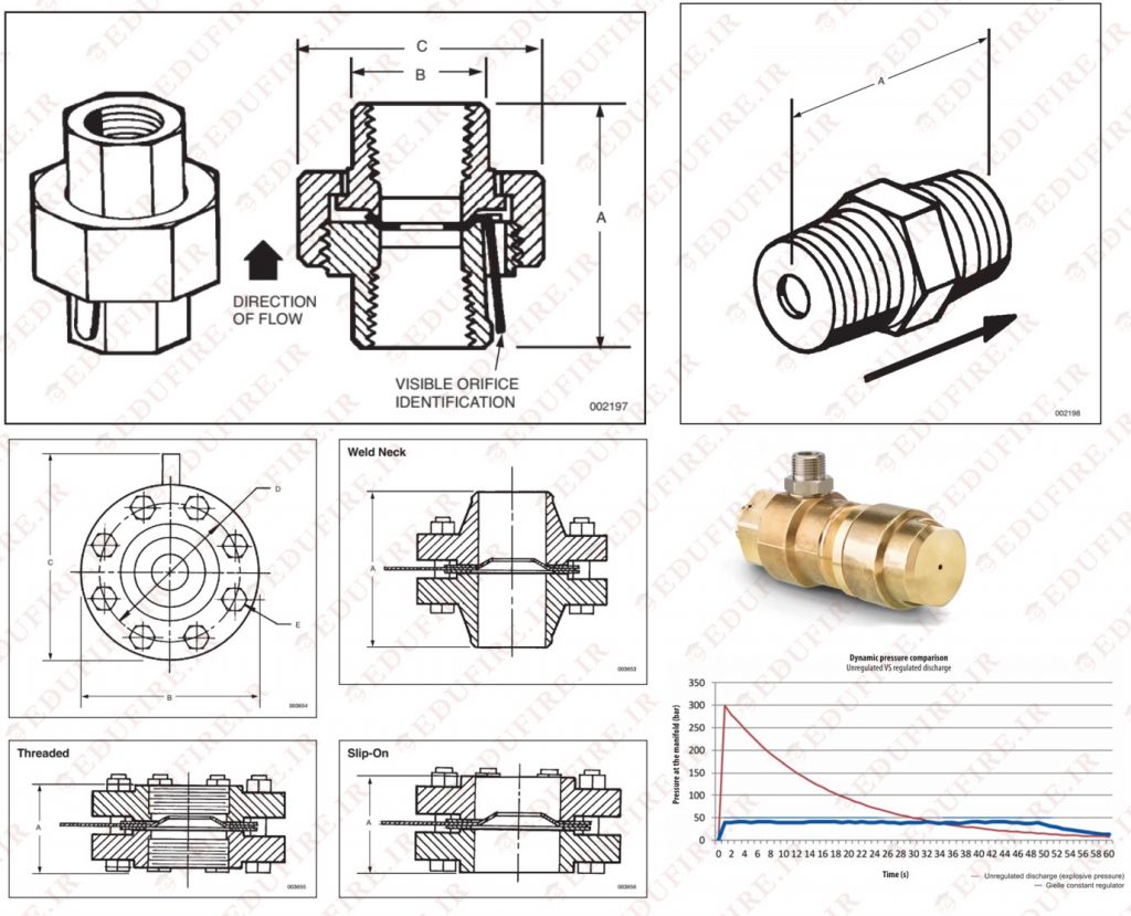
- Pressure Gauge: The pressure gauge is essential for monitoring the pressure inside the container and must be calibrated according to NFPA 2001 standards. If the pressure drops by 5% from the initial pressure, the cylinder should be refilled or exchanged. This equipment is crucial for detecting leaks and ensuring the system remains functional.
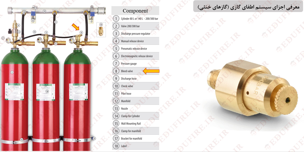
- Bleed valve: Bleed valve: This valve is installed on the cylinder to alert us to unwanted discharge of the slave cylinders. If a leakage occurs in any of the cylinders, the other cylinders may get pneumatically actuated. By installing this valve at the end of pilot hoses, if minor leakage occurs, it will leak out of this valve instead of actuating the other cylinders. This valve normally closes …..
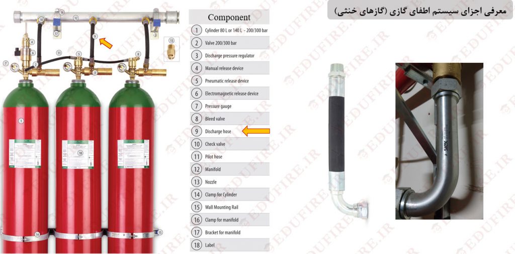
- Discharge hose: The discharge hose is used for directing the gas into the collector or pipes. It is available in two materials: rubber and metal. According to NFPA 2001 standards, rubber hoses need to be tested or replaced every 5 years. The following figure represents these two types.
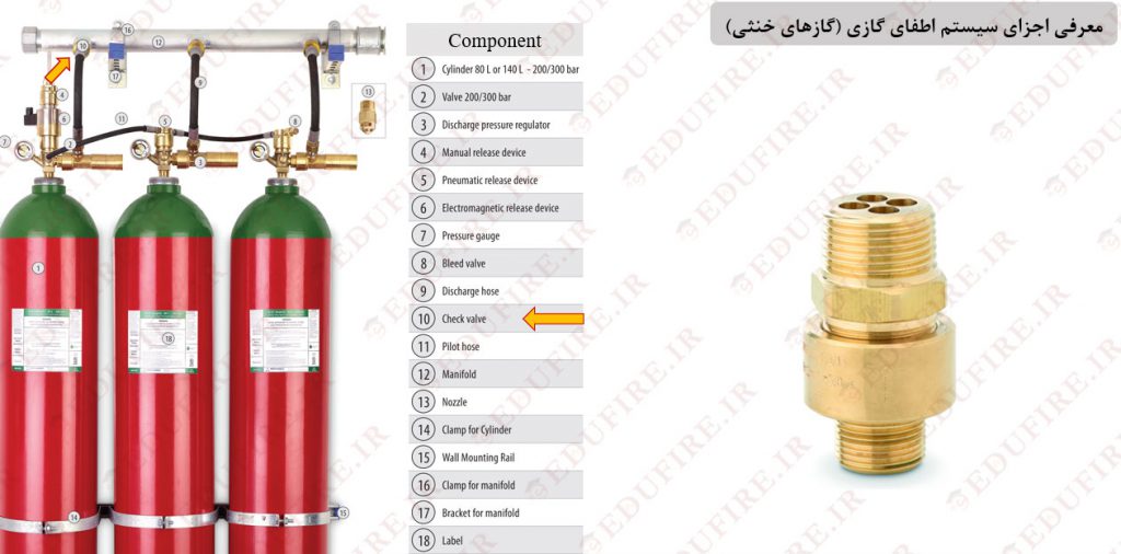
- Check valve: When a bank of containers (several containers protecting a single area) is present, a check valve should be installed at the inlet of the manifold for each container. This prevents the waste of the extinguishing agent, as in the absence of a check valve, the agent may flow into empty containers.
- Pilot hose: The pilot hose is used to transfer a percentage of the gas from the master cylinder to other cylinders for pneumatic actuation.

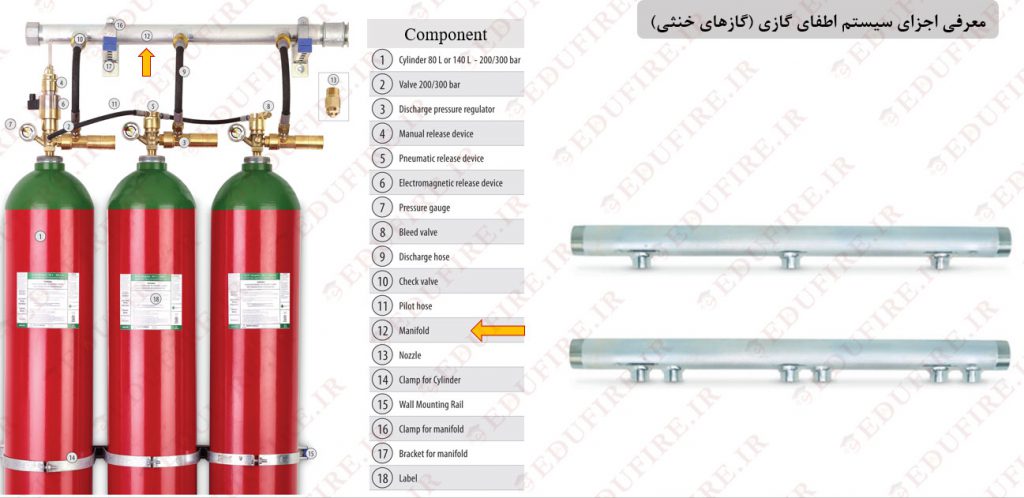
- Manifold or collector: The manifold or collector is used to collect the agent from all containers and direct it to the piping network.
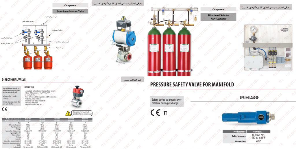
Note: If the route from the cylinder to the piping network is clogged for any reason (e.g., when a directional valve is installed), a relief valve should be used in this route.
Note: Some manufacturers build and deliver the manifold to the customer. Alternatively, the manifold can be manufactured on-site at the project using SCH. 80 ASTM A53. (For more information regarding the type of pipe required, refer to the manufacturer’s manual)
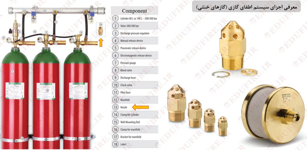
- Nozzles: Nozzles in an inert gas system (IG) are responsible for delivering the extinguishing agent into the protected area. Choosing the correct type of nozzle requires careful attention, as the amount of agent exiting the nozzle is determined by tee-junction connections, piping configuration, and orifices. In some nozzles, a plate is placed before the nozzle, which needs to be drilled to the proper size according to hydraulic calculations. However, some manufacturers supply nozzles in different pre-drilled sizes, in which case using an orifice is not applicable. Recently, scientists have developed a new type of nozzle, known as the “Silent Nozzle,” to reduce the effects of noise on electronic sensitive facilities such as hard disks.
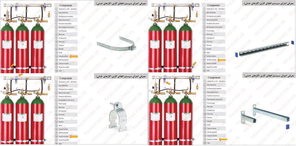
- Cylinder brackets and manifold support: Due to the high pressure of the cylinders containing the extinguishing agent, it is crucial to secure them to ensure the safety of the cylinder area. For this purpose, brackets and clamps are used. Additionally, it is necessary to secure the piping network and the manifold using pipe-supporting materials.
Note: It is recommended to use two brackets for large cylinders (more than 26 liters), and the brackets should be installed on the rail and fixed to the load-bearing wall.
Note: When using two brackets or clamps, one should be installed at 1/3 of the height of the cylinder and the other at 2/3.
- Cylinder label: One of the most important features of a cylinder is the label on it, which is either a paper type glued to the surface of the cylinder or engraved on a metal plate. This label contains crucial information such as the type of stored agent, the date of filling, the weight of the agent, the weight of the cylinder, and more. Some examples of these labels are visible below:
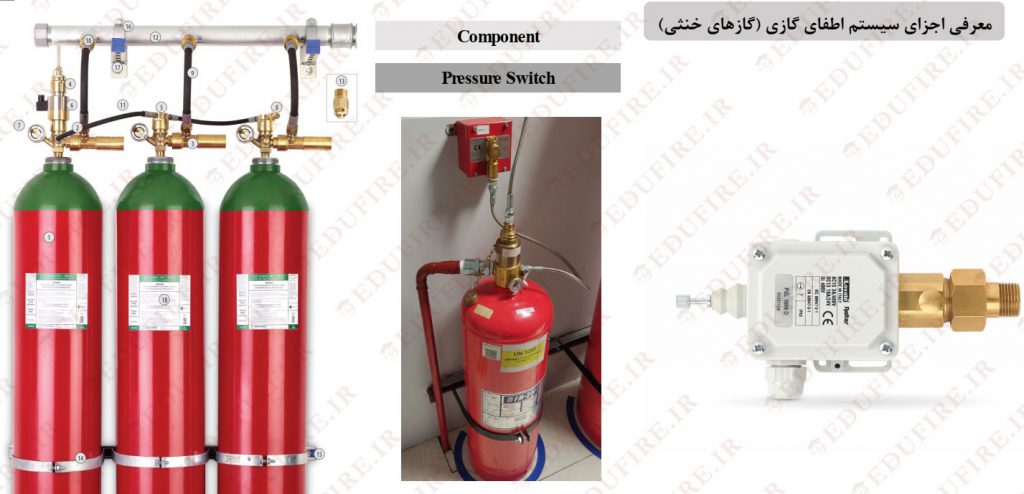
- Pressure switch: In automatic gaseous extinguishing systems (whether IG, F-K-5-1-12, HFC227EA, or other extinguishing agents) that include a manual actuator, a pressure switch is essential. This is because the system may be manually actuated before the fire alarm system detects the fire. In such cases, the pressure switch sends a signal to the fire alarm control panel, causing the sirens to activate and alerting occupants to the suppression system being triggered. These pressure switches typically send out the signal at a working pressure of 2 bars, corresponding to the system’s pressure increase.
- Directional or selector valve: This valve is installed in the network when multiple areas are being protected using a single or a bank of cylinders. Directional valves can be actuated pneumatically, electrically, or manually.
Note: These valves are usually expensive and are recommended only when the system consists of a higher-than-usual number of cylinders.
Note: When using this approach, the client should be aware that if a fire initiates in one area and is suppressed by the implemented system, other areas are no longer protected, unless reserve cylinders are also installed.
Note: In the case of using selector valves, relief valves should be installed on the route from the cylinder to each protected area.
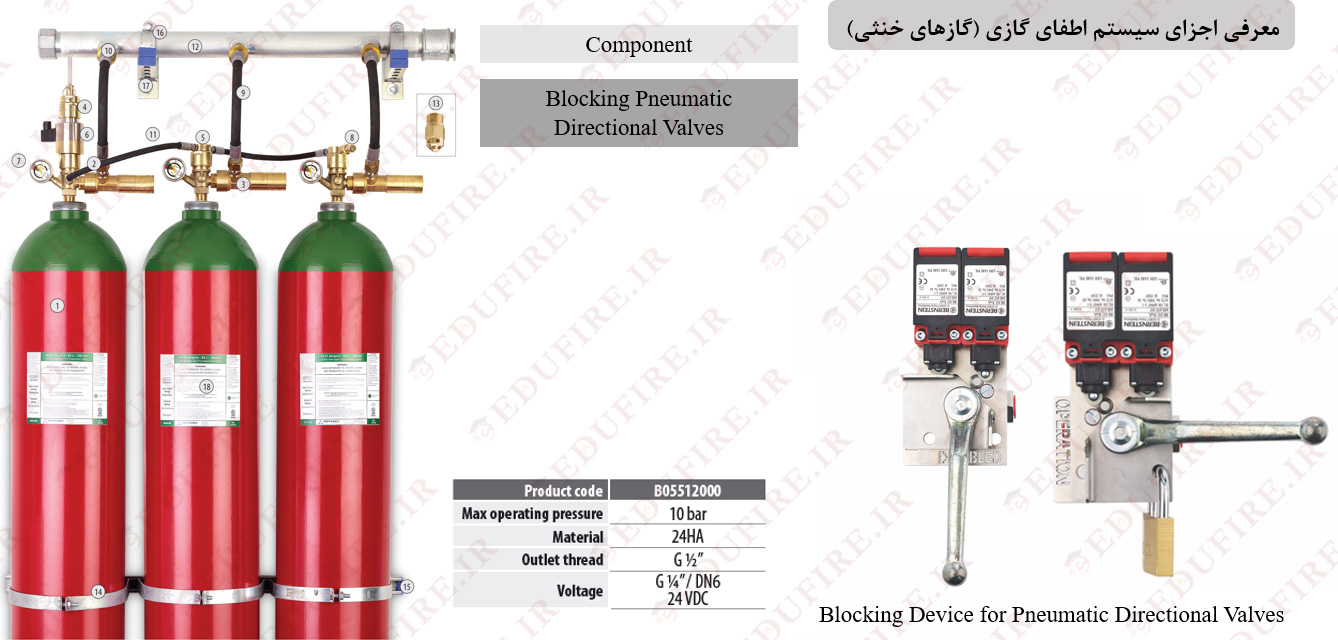
- Lockout valve or blocking pneumatic directional valve: This valve is primarily used during maintenance. When the lockout valve is closed, the extinguishing agent will not discharge into the protected area, even if the system is actuated. Lockout valves are used in CO2 systems to block the flow of the extinguishing agent, providing operators inside the protected area enough time before the agent is discharged in case of a fire.
Note: Lockout valves must be installed in CO2 systems according to NFPA 2001, unless the authority having jurisdiction permits otherwise.
Note: If the design concentration exceeds the requirements of NFPA 2001, a lockout valve must be installed.
Design, Consultation, Supply, and Installation of the Proper Automatic Gaseous Fire Suppression System
The proper design and functionality of a gaseous fire suppression system depend heavily on the characteristics and type of occupancy it is intended for, such as room temperature, discharge time, potential hazards, and more. Contact us for inspection and consultancy services for automatic gaseous fire suppression systems.